


The Boat Ignition Switch Wiring Diagram You Need: Troubleshooting and Installation Guide
Boating is a fantastic pastime, offering freedom and adventure on the water. But a dead engine can quickly transform a sunny day into a frustrating experience. One of the most common culprits behind engine failure is a faulty ignition switch or its wiring. Understanding the boat ignition switch wiring diagram is crucial for troubleshooting problems, performing repairs, and ensuring your boat starts reliably every time. This guide provides a comprehensive overview, helping you navigate the intricacies of your boat’s electrical system and keep you safely cruising.
Understanding the Role of the Boat Ignition Switch
The ignition switch is more than just a key that unlocks your boat’s engine. It’s a central control point, directing power to various critical components. When you turn the key, the switch completes specific circuits, initiating the following key functions:
- Powering the Ignition System: This includes the coil (if applicable), which generates the high voltage needed for spark plugs.
- Activating the Starter Motor: This engages the engine to begin the combustion process.
- Providing Power to Accessories: This can include gauges, lights, and other onboard electronics.
- Safety Features: Many switches incorporate safety features like a kill switch connection to shut off the engine in emergencies.
A malfunctioning ignition switch or incorrect wiring can lead to a variety of issues, including:
- No Start: The engine fails to turn over.
- Engine Stalling: The engine unexpectedly shuts off while running.
- Intermittent Operation: The engine starts and stops erratically.
- Loss of Accessory Power: Gauges, lights, and other accessories cease to function.
Decoding the Boat Ignition Switch Wiring Diagram
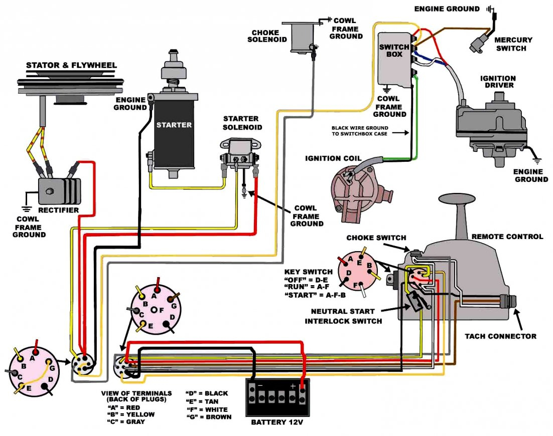
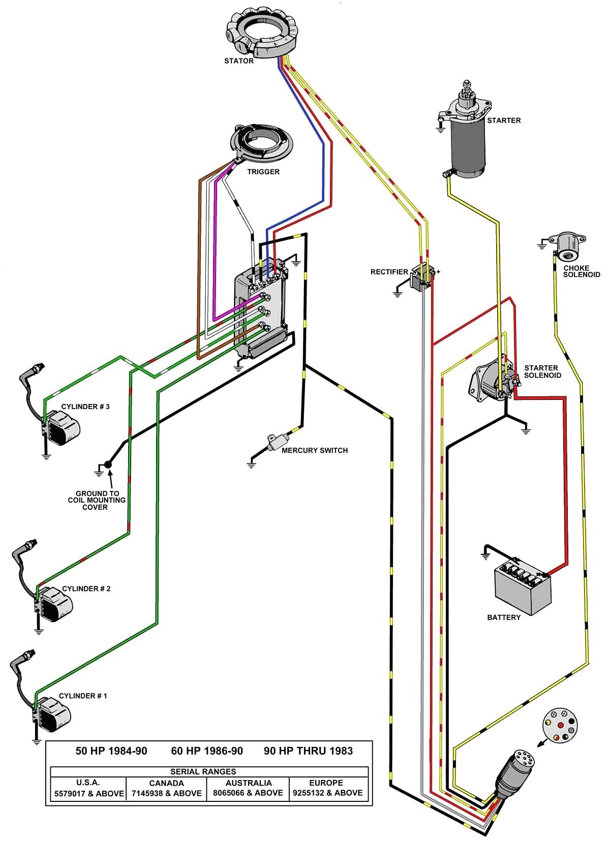
The boat ignition switch wiring diagram is your roadmap to understanding and repairing your boat’s electrical system. While diagrams can vary slightly depending on the engine type (inboard, outboard, etc.) and manufacturer, the basic principles remain the same. You’ll typically encounter these common wire colors and their corresponding functions:
- BATT (Battery): Typically Red or Black. Provides constant 12V power from the battery. This is the main power source.
- IGN (Ignition): Typically Purple. Provides power to the ignition coil, gauges, and other accessories when the key is in the “ON” position.
- START: Typically Yellow or Yellow/Red. Provides power to the starter motor solenoid when the key is turned to the “START” position.
- ACC (Accessory): Typically Brown. Provides power to accessories like lights, radios, and other electrical components when the key is in the “ON” position.
- GND (Ground): Typically Black. Provides the ground connection for electrical circuits.
Important Note: Always disconnect the battery’s negative terminal before working on any electrical components to prevent accidental shorts and potential damage.
Steps for Using a Boat Ignition Switch Wiring Diagram
- Locate Your Diagram: Find the wiring diagram specific to your boat’s engine and model. This information is often found in your boat’s owner’s manual or online. You can often find these diagrams by searching online using the engine and boat model, such as “[Engine Model] ignition switch wiring diagram”.
- Identify the Terminals: Locate the terminals on your ignition switch. They’ll be labeled with abbreviations like those listed above.
- Trace the Wires: Carefully trace each wire from the ignition switch to its corresponding component (battery, starter motor, etc.) using the diagram as a guide.
- Check for Continuity: Use a multimeter to check for continuity in the wires. This helps identify broken wires or faulty connections.
- Inspect for Corrosion: Look for corrosion on wire terminals, connectors, and the ignition switch itself. Clean or replace corroded components.
- Test the Switch: Use a multimeter to test the switch’s functionality. The switch should show continuity between the appropriate terminals when the key is in the “ON” or “START” position.
Troubleshooting Common Ignition Switch Problems
- Engine Doesn’t Crank: Check the battery, starter motor, and wiring to the starter solenoid. Inspect the wiring for the START terminal.
- No Spark: Check the ignition coil, distributor (if applicable), and wiring to the ignition coil. Inspect the wiring for the IGN terminal.
- Accessories Not Working: Check the wiring to the ACC terminal and the associated accessories.
- Engine Stalls: This could be caused by a faulty ignition switch, loose connections, or problems with the fuel system.
Replacing a Boat Ignition Switch: A Step-by-Step Guide
- Disconnect the Battery: Disconnect the negative battery terminal. This is crucial for safety.
- Remove the Old Switch: Disconnect the wires from the old ignition switch, noting their positions or taking a picture for reference.
- Mount the New Switch: Install the new ignition switch in the existing mounting hole.
- Connect the Wires: Connect the wires to the new switch, using the wiring diagram as a guide. Ensure all connections are secure.
- Test the System: Reconnect the battery and test the ignition switch by turning the key to the “ON” and “START” positions. Verify that all accessories are functioning correctly.
Safety Considerations
- Always disconnect the battery before working on any electrical components.
- Use the correct gauge wire for your boat’s electrical system. Consult your boat’s manual or a marine electrician for recommendations.
- Use marine-grade connectors and terminals to prevent corrosion.
- Double-check all connections to ensure they are secure.
- If you are not comfortable working with electrical systems, consult a qualified marine technician.
Conclusion: Keeping Your Boat Running Smoothly
Understanding and using the boat ignition switch wiring diagram is essential for maintaining a reliable and safe boating experience. By following the steps outlined in this guide, you can troubleshoot problems, perform repairs, and ensure your boat’s engine starts and runs smoothly. Remember to prioritize safety, use the correct tools and materials, and don’t hesitate to seek professional help if needed. With a little knowledge and attention, you can keep your boat running and enjoy countless hours on the water.
Frequently Asked Questions (FAQs)
1. Where can I find the wiring diagram for my boat’s ignition switch?
You can find the wiring diagram in your boat’s owner’s manual, engine service manual, or online by searching for your specific engine and model, such as “[Engine Model] ignition switch wiring diagram”.
2. What if the wire colors on my boat don’t match the standard colors listed?
Wire colors can vary. Always refer to your specific boat’s wiring diagram for accurate identification of wire functions. If a diagram is unavailable, trace the wires from the ignition switch to their components to determine their function.
3. Can I use automotive-grade wire and connectors on my boat?
While automotive-grade wire and connectors may seem similar, it’s highly recommended to use marine-grade components. Marine-grade components are specifically designed to withstand the harsh marine environment, including moisture, corrosion, and vibration.
4. How do I test if my ignition switch is bad?
Use a multimeter to test for continuity across the ignition switch terminals when the key is in the “ON” and “START” positions. The switch should provide continuity between the corresponding terminals in the diagram.
5. What tools do I need for this project?
You will need a multimeter, wire strippers, crimpers, screwdrivers, and potentially a soldering iron and heat shrink tubing. Always wear safety glasses.
